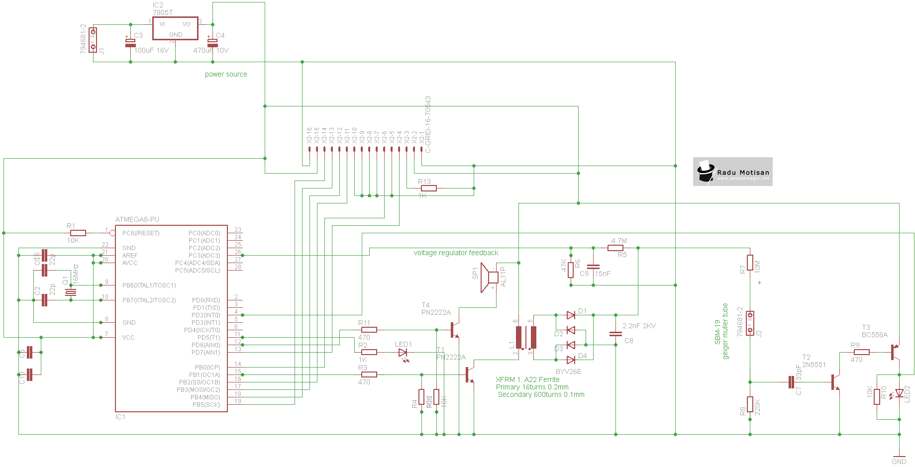
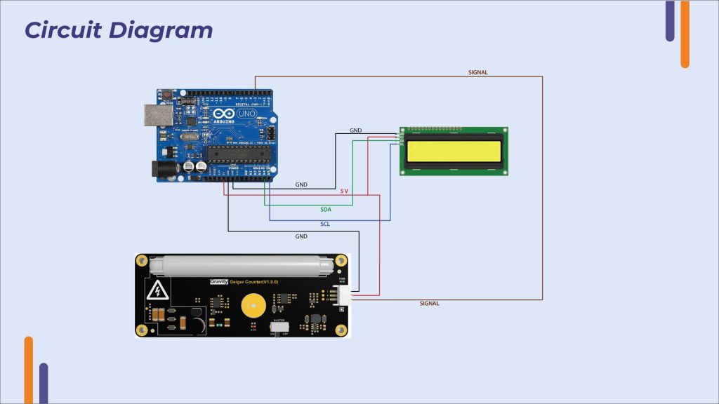
Geiger counter and radioactivity Circuit Diagram The electronic circuit of a Geiger-Müller counter. MC34063 is a DC/DC converter used to produce required high voltage, one of it's advantage over a simple NE555 or similar generators in this circuit is that it can monitor the output voltage and adjusts parameters to make it stable (R3, R4, R5, C3).

The 555 timer then drives a small speaker directly, making a 'click' noise each time the Geiger tube detects radiation. Use an IC socket for the 555 timer chip, so you don't fry the chip when trying to solder it into the circuit, also it makes it easier to replace if you make a wrong connection and fry the chip. This DIY nuclear radiation detector can measure and detect alpha, beta, and gamma radiation. Here we used muller tube, Geiger counter & ESP32. Making Portable Radiation Detection Device. By Ashwini Sinha. December 13, 2022. Telegram. Facebook. Linkedin. Here we used the muller tube and Geiger counter circuit to get the nuclear radiation.
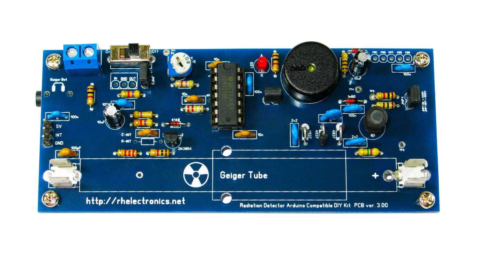
DIY Build Your Own Geiger Counter Circuit Diagram
Before mounting the PCB inside the case, check to make sure the entire Geiger Counter circuit functions. Background radiation will cause the Geiger Counter to click about 12—22 times a minute depending on your location. When you are satisfied that the circuit is working properly we can mount the circuit inside the case.
Build Your Own Easy Radiation Detector Using a Geiger Counter Module Introduction Radiation detectors are essential instruments for identifying high-energy […]
Homemade Geiger Counter Circuit Diagram
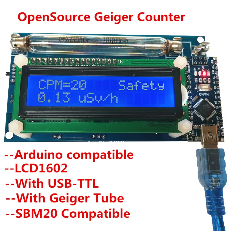
Geiger counter, also known as Geiger-Müller (G-M) counter, detects ionizing radiation such as alpha particles, beta particles and gamma rays using the ionization effect produced in a Geiger-Tube. The Geiger-Tube (GMT or GT) is filled with an inert gas such as helium, neon, or argon at low pressure, to which a high voltage is applied.

The circuit diagram is shown in Figure 6. The parts needed are shown in Figure 7 and parts lists broken down by subassembly are given at each step. You will be assembling the circuit on a printed circuit board (PCB), the top of which is shown in Figure 8. In the subsequent steps, components involved in the active step will be shown in full